Previous Steps. This is final tutorial of How to Sketch, Draw and Modeling Connecting Rod in Solidworks. In this tutorial we want to Sketch, modeling or draw an up side part of connecting rod in solidworks. Let us start.

- Open solidworks program. Choose part mode. Insert sketch on front plane and draw sketch like shown. You can use circle, line, centerline, trim and also mirror or offset command if you need.

- Use trim again, so your draw like shown.

- Draw circle with 52mm and draw two lines.

- Use trim command, so your draw like shown.

- Now, extrude sketch 11mm. On extrude boss properties click mid plane on direction tab.

- Insert sketch on front face of body. Draw sketch like shown with radius19mm and 21mm. Use circle, line and trim command to help you.

- Use extrude command with 2mm. After that mirror it to the back side or make same action to the back side.

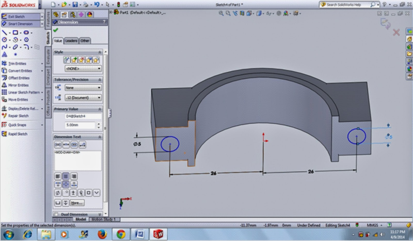
- Insert sketch on the top face of body. Draw two circles with diameters 5mm like shown.
- Use extrude cut command, choose through all to make hole.

- Use fillet command with radius 2mm and 0.5mm.

- Insert sketch on top surface. Draw sketch like shown.

- Use revolved cut command. On axis of revolution, click center line.

- Your job done. Here is your model.

Tidak ada komentar:
Posting Komentar