In this tutorial, you will learn How to Draw and modeling Oil Canal of Crankshaft in solidworks. After in the previous tutorial, we have finished sketch, draw, modeling connecting rod, now we continue how to draw and modeling connecting rod Oil Canal in Solidworks.

Let us start and enjoy it.
1. Open solidworks program. Open your connecting rod file. First you must insert sketch on face body like shown.

Draw Circle with diameter 4mm and center line on center of circle follow z coordinate.

2. Use revolve cut command.

3. Insert sketch again on same surface. Draw circle with diameter 4mm like shown.

4. Use extrude cut command like shown.

5. Insert sketch on front plane.

6. Choose front view on view orientation. Use center line, line command and smart dimention command, draw sketch like shown. Or you can use offset command if needed.

7. Use extrude cut command.

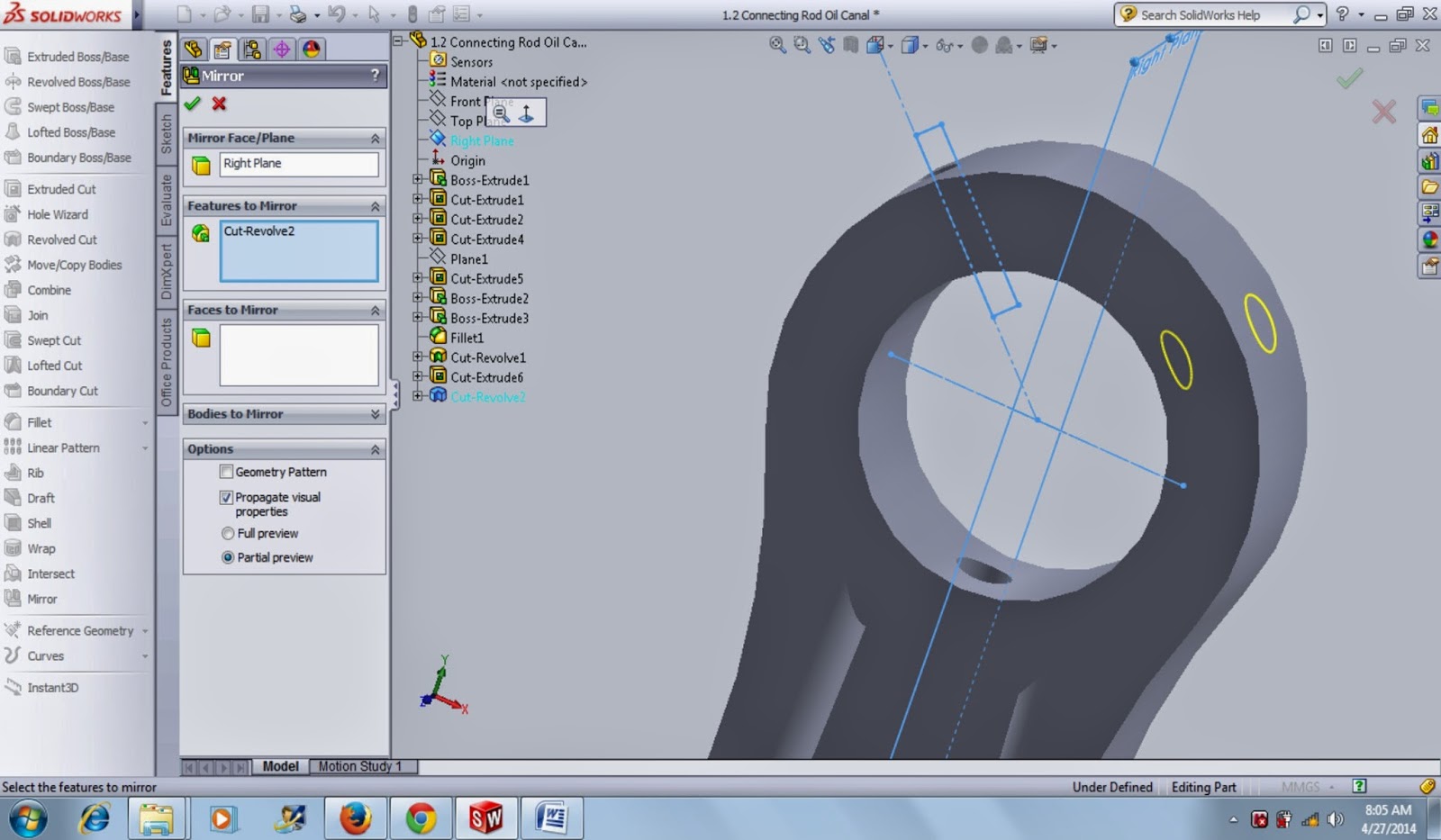
8. Click mirror command. On mirrof face/plane tab, click right plane on tree feature, confirm.
9. Use fillet command. Radius 1mm.


10. Your Oil Canal of Connecting Rod done.

Now, how to draw and modeling oil canal of connecting rod have finished. In the next tutorial we will learn more model of part engine. Okey, keep always follow the tutorial. I hope you will improve your solidworks skill to be master. Please comment if you want to ask or share.
Let us start and enjoy it.
1. Open solidworks program. Open your connecting rod file. First you must insert sketch on face body like shown.
Draw Circle with diameter 4mm and center line on center of circle follow z coordinate.
2. Use revolve cut command.
4. Use extrude cut command like shown.
5. Insert sketch on front plane.
6. Choose front view on view orientation. Use center line, line command and smart dimention command, draw sketch like shown. Or you can use offset command if needed.
7. Use extrude cut command.
8. Click mirror command. On mirrof face/plane tab, click right plane on tree feature, confirm.
9. Use fillet command. Radius 1mm.
10. Your Oil Canal of Connecting Rod done.
Now, how to draw and modeling oil canal of connecting rod have finished. In the next tutorial we will learn more model of part engine. Okey, keep always follow the tutorial. I hope you will improve your solidworks skill to be master. Please comment if you want to ask or share.
Tidak ada komentar:
Posting Komentar