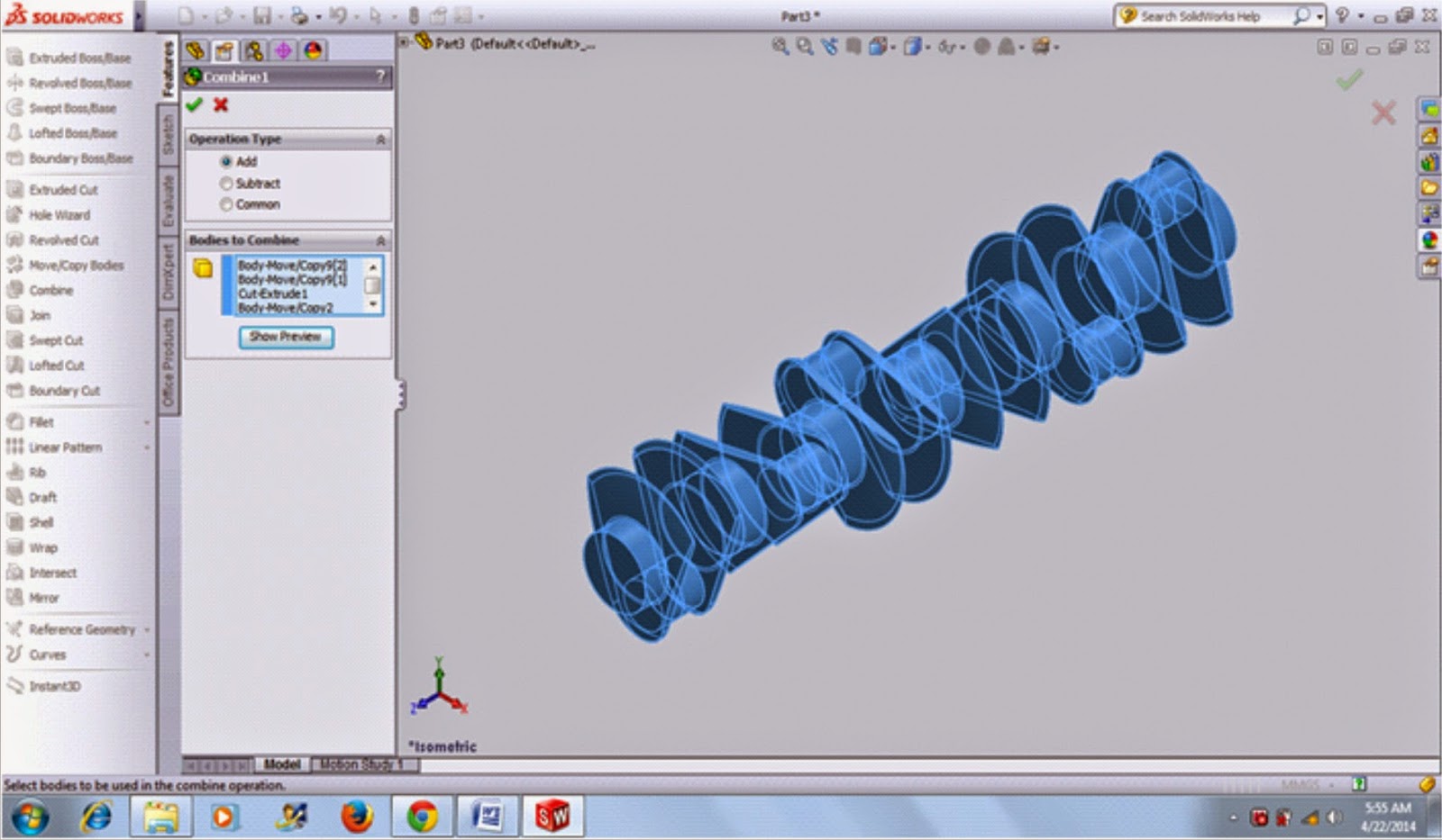
In this tutorial, you will learn how to sketch, modeling or draw crankshaft in solidworks. We will guide you step by step so you can use this tutorial with easly. And also you can Modeling or drawing crank in solidworks.
Let us start and enjoy it.
1. Open solidworks program. Click part mode. Insert sketch on the right plane. Draw sketch like shown.
2. Use Revolved Boss Command. The axis line of the revolution click horizontal line on the bottom sketch. On the direction, input value 360 deg.
3. Insert Sketch on front face of body. Draw circle with 60mm diameter. Extrude it 20mm.
4. On the back side of the body. Draw circle with diameter 38mm like shown, and extrude it 20mm.
5. Draw sketch like shown. Use circle, line, centerline, smart dimension and mirror command.
6. Use trim command.
7. Click isometric view to get view more comprehenship. Use extrude cut command, click flip side to cut.
8. On the right view, use mirror Comand. If you can not use it, choose move / copy bodies command. Click translate / rotate on move / copy bodies properties. Click copy box and slide up to 47.5 mm.
9. Now, rotate up to 180 degrees. Use move / copy bodies command. Click translate / rotate on move / copy bodies properties. Do not click on copy box and choose rotate tabe. On Y axis, rotate up to 180 degrees.
10. Use move / copy bodies command. Click model and click copy box. Input 5 on /# box. Click translate. On Z axis, input 95mm.
11. With move / copy bodies command again, rotate sixth body 180 degrees. Note, for rotate, do not click copy box.
12. Rotate 5th body 300 degrees.
13. Rotate 4th body 60 degrees.
14. Rotate 3th body 120 degrees.
15. Rotate second body 240 degrees.
16. Now we want to combine all part. Use combine command. Click combine command and select all. Choose add option.
Now, the main body of crankshaft have been finished. Next, we want to sketch, draw and modeling crankshaft with connection point. I hope you can follow this tutorial like easly. Do not hesitate to comment if you face difficulty.More practice, more good.
Let us start and enjoy it.
1. Open solidworks program. Click part mode. Insert sketch on the right plane. Draw sketch like shown.
4. On the back side of the body. Draw circle with diameter 38mm like shown, and extrude it 20mm.
7. Click isometric view to get view more comprehenship. Use extrude cut command, click flip side to cut.
10. Use move / copy bodies command. Click model and click copy box. Input 5 on /# box. Click translate. On Z axis, input 95mm.
11. With move / copy bodies command again, rotate sixth body 180 degrees. Note, for rotate, do not click copy box.
12. Rotate 5th body 300 degrees.
13. Rotate 4th body 60 degrees.
14. Rotate 3th body 120 degrees.
15. Rotate second body 240 degrees.
16. Now we want to combine all part. Use combine command. Click combine command and select all. Choose add option.
Now, the main body of crankshaft have been finished. Next, we want to sketch, draw and modeling crankshaft with connection point. I hope you can follow this tutorial like easly. Do not hesitate to comment if you face difficulty.More practice, more good.


Tidak ada komentar:
Posting Komentar